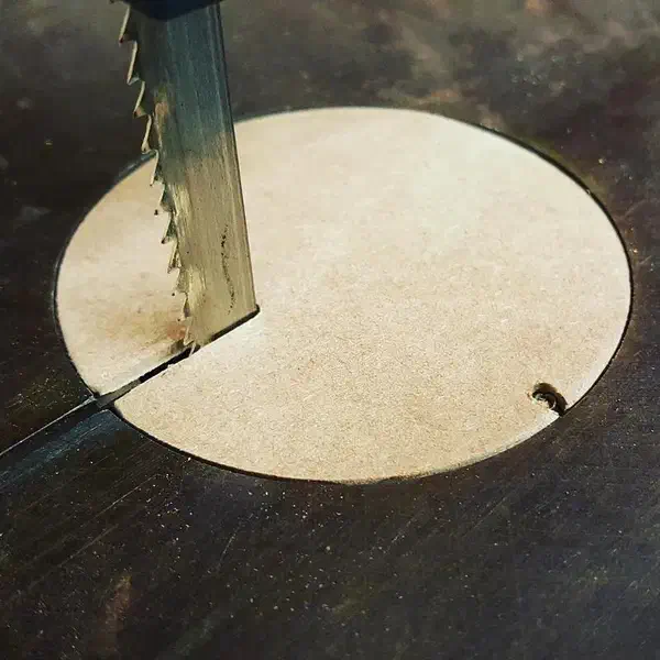
The animation below shows drawing an MDF bandsaw throat plate from scratch in Easel. The circular plate rests on a table ledge; its front slit admits the blade and its left notch clears a locating pin. Measure your own saw’s opening, ledge, blade and locating features before adapting this example. Every saw dimension, clearance and stock size below is an untested design assumption. First define the mating saw, not the plate: use a common XY frame centered at X42.75, Y42.75 mm, with the front toward decreasing Y, and Z0 at the tabletop. The opening is 86 mm across; the ledge’s inner opening is 78 mm across, giving a 4 mm radial ledge width, with its support face at Z−2.6 mm. The blade is centered at X42.75, Y20 mm, 0.6 mm thick across X and 6 mm wide along Y, so it occupies X42.45–43.05 and Y17–23 mm. Its entry path follows X42.75 from the front opening edge at Y−0.25 to Y23 mm. Model the locating pin’s occupied envelope at X−0.25–4, Y41.75–43.75 and Z−2.6–0 mm: a 4.25 mm inward projection and 2 mm width. The 85.5 mm plate diameter and 2.6 mm finished thickness follow Timothy Wood’s published plate. Now draw the plate: 86 − 0.5 mm diametral clearance = 85.5 mm, centered on the opening, leaving 0.25 mm radial clearance. Its overlap on the ledge is (85.5 − 78) ÷ 2 = 3.75 mm, except at the slit and notch. Use 150 × 150 × 19.4 mm MDF stock and the selected 1/16-inch fishtail spiral cutter; position the circle’s lower-left corner at stock X20, Y20 mm, translating all the assembly coordinates by that same offset. Pocket the full circle 16.8 mm deep, then add the outside through-profile: 19.4 − 16.8 = 2.6 mm remains. Place that remaining plate underside on the assumed Z−2.6 mm ledge to put its top at Z0; neither flushness nor retention has been physically tested. Cut the blade slot through at assembly X40.75–44.75, Y0–26 mm. Its 4 mm width clears the assumed 0.6 mm blade by (4 − 0.6) ÷ 2 = 1.7 mm per side; the slot opens at the circular front edge and reaches 26 − 23 = 3 mm beyond the blade’s back edge. Cut the locating notch through at X0–6, Y40.75–44.75 mm. Its 4 mm width clears the assumed 2 mm pin by 1 mm per side, and its inner end clears the pin’s X4 tip by 6 − 4 = 2 mm; the pin projects into the notch without occupying plate material. The cutter’s rounded inside corners stay clear of both assumed envelopes. Remove the profile tabs, check the plate against your table opening, and trim or revise the design to your own measurements. With the saw unplugged, check that the insert sits flush and stays retained before running the saw.
Recorded in the Easel editor, playing at 4× real speed.
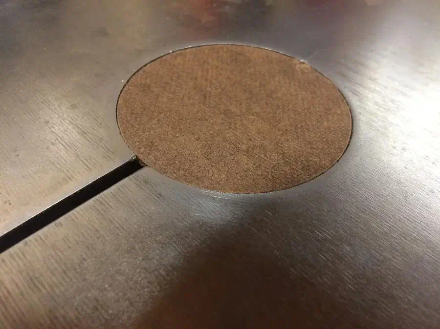
PR Smith documents 0.22-inch hardboard and a 0.12-inch recess leaving the thickness for his 0.10-inch table step. His shared file contains a single workpiece with two concentric circular outline cuts: the outer through-cut and a smaller outline at the recess depth; clear the area inside the smaller outline to the recess depth before fitting.
Timothy’s MDF insert is drawn for his 1970 Craftsman bandsaw: 85.5 mm across and 2.6 mm finished thickness, with a blade-entry slit and locating notch. His shared design contains one workpiece with the outer circle, recessed center, slit and notch. His instructions start with measuring the opening, depth, blade position and alignment features, then adjusting the design.
 Bandsaw Zero Clearance Insertby PR Smith