Make an audio-equipment rack

Plan an audio-equipment rack in Easel around its metal rails, equipment depth and wooden joints.

See the finished builds

Start from a blank workpiece

Design your own audio-equipment rack

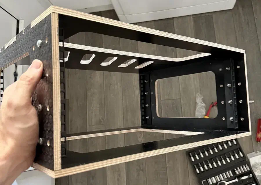
The animation below shows drawing a plywood audio-equipment rack sleeve from scratch in Easel. Four panels surround separate rack rails; purchased wooden battens and screws join the shell, and cage nuts and equipment screws hold the audio unit. This is an untested reference assembly, not a verified commercial rail model. Assume rails 178 mm high with 24 mm front flanges, 2 mm metal and 40 mm-deep side returns. Equipment has a 482.6 × 176 mm faceplate with holes 465.1 mm apart, a centered 440 mm-wide body 300 mm deep, and 50 mm of rear cable space. In 9 mm plywood, draw two 522 × 400 mm top/bottom panels and two 400 × 190 mm sides. Sides fit between top and bottom, leaving 504 mm clear width and 190 mm height. Center the faceplate vertically with 7 mm above and below; its 21.4 mm total width allowance is inside the side walls. The rail flanges leave a 456 mm body opening and their hole centers lie 19.45 mm inward from each inside wall, giving the 465.1 mm mounting span. Cut four separate 20 × 20 mm battens to 320 mm length. Run them along the upper and lower inside side corners, starting 60 mm behind the front and ending at 380 mm depth. This puts them 55 mm behind the reference faceplate’s 5 mm rear face. At batten depth the 464 mm gap between left/right battens exceeds the centered 440 mm body by 24 mm; the equipment passes between them, not through their 150 mm vertical gap. Keep the body’s rear cable envelope within 355 mm of the front. Put top/bottom screw guides 19 and 503 mm across each panel at 100 and 340 mm depth, over the battens. Side-to-batten guides are at depths 120 and 320 mm and heights 10 and 180 mm. These staggered positions keep the two screw directions apart. Clamp the shell and battens, then drill 2 mm batten pilots through the 3.5 mm guides for 3 × 25 mm wood screws. Rail fixing holes are separate 4.5 mm holes, 30 mm behind the front at heights 20 and 170 mm; use M4 bolts, washers and locknuts, keeping their inward projection within 12 mm. Remove profile tabs and fit the rails before equipment. Confirm all reference hardware dimensions, ventilation and loaded strength on a mock-up; the recording demonstrates panel geometry and fixing positions, not physical assembly or transit testing.

Recorded in the Easel editor, playing at 4× real speed.

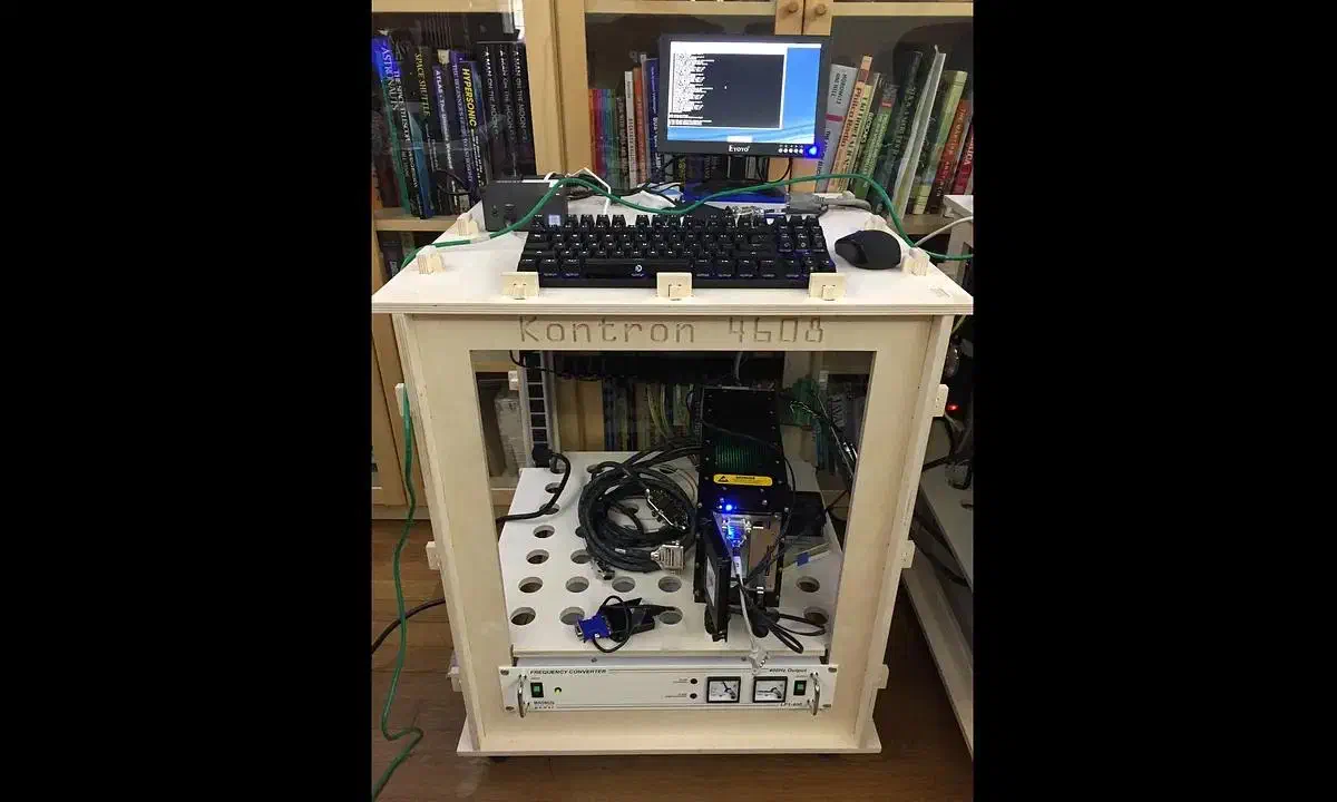
A compact rail sleeve or a furniture-scale rack

A compact sleeve holds separate metal rack rails, while a larger open rack adds shelves around equipment. Choose its joints and sheet thickness for the intended assembly.

See more rack search results →

Drill guides and screw the notched joints

Log in to post a question in the project discussion; replies are not guaranteed.

Drill guides and screw the notched joints

Jamie Mckivitt says he drills guide holes by hand and screws each notched joint: four on each side and six at the top and bottom.

Project notes by Jamie Mckivitt: read the source.

From 4U Fly Rack Sleeve for a Peli Case by Jamie Mckivitt.

Ask a question

Start creating with your CNC

Create your free Easel account and connect your machine in minutes.